


The latest trend for semiconductor device manufacturers is to add several high-speed MIPI® specification-based ports to a single device. This enables feature-rich implementations of imaging- and display-intensive applications, although it also poses significant challenges for production test engineers who are tasked with creating high-fault coverage testing solutions on automated test equipment (ATE). Such fault coverage often entails creating a parallel, at-speed, system-oriented functional test while simultaneously grappling with the limitations of legacy ATE and the complexity of the MIPI protocols being tested. This post describes production testing methodologies of MIPI-based devices on any ATE platform, whether it is at the wafer test stage or the final test stage.
Test as the Last Gate Before Shipping Product
Testing is a final step that manufacturers perform before shipping their products, and its goal is to screen for defects that may be introduced during the fabrication process. However, significant challenges have emerged recently as ATE technology typically lags features that are required to accommodate new product introductions in the technology industry. For example, MIPI specifications challenge ATEs because of their low power (LP), high speed (HS) and multilevel signaling features, giving rise to significant implications on testing devices in production.
Conventional ATE is useful because of its integrated nature and the robust software environment that comes with it. But, it typically only provides either low or high impedance, and low or high voltage—not both. Thus, configuring conventional ATE for the MIPI LP and HS signaling modes has limitations. More importantly, most ATE cannot keep up with the newest MIPI D-PHYSM data rates at 2.5 Gbps, 4.5 Gbps, and even 6.5 Gbps.
“Golden device” test methodology, on the other hand, uses a load board-mounted copy of the device under test (DUT) as a means for performing a limited interoperability test during mass production. This represents a point solution because golden devices don’t necessarily provide superior quality for final testing nor are they instrument grade.
A hybrid test module puts an ATE channel card on a load board and is similar to a low-cost golden device that connects ATE to DUT. The test module integrates features for quality testing of MIPI interfaces. For instance, test modules can enable a dedicated protocol fabric to handle protocol content and packet data communications to/from the DUT; and the same module can also include LP, HS and multilevel signaling for a physical layer (PHY) complying with, say, the MIPI C-PHYSM specification. 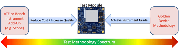
Figure 1. A hybrid solution between ATE and golden device test methodologies offers the best of both worlds.
(Image: Introspect Technology)
MIPI Production Test Challenges
MIPI PHY specifications are characterized by LP signaling, where impedance is higher than normal and HS signals, where voltage levels are extremely low, with low impedance.
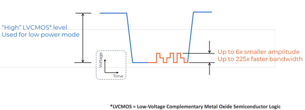
Figure 2. Real-time intermixing between low-voltage signaling at very high speeds and high voltage signaling at high impedance levels means that MIPI devices are difficult to test on typical ATEs.
(Image: Introspect Technology)
Another challenge is that HS signals often run 200 times faster than a LP signal, and the transition between the two modes happens in the span of mere nanoseconds. Testing the HS millivolt signaling at the receiver, in particular, can be especially difficult to achieve with conventional ATEs.
Switching also challenges ATEs and the test engineers who are tasked with programming them. For example, a test engineer may decide to use a 3 Gbps ATE channel card and put switches on the load board for MIPI testing. The problem is that the selected microwave switches are designed for low-impedance switching, but not for dynamic termination. Placing them on a high-impedance load results in waveform anomalies that potentially violate the rapid switching requirements of MIPI devices. Both scenarios are shown on the right in Figure 3. Switching also occurs inside the DUT, going from high to low impedance, creating artifacts on the signal under test.
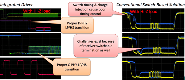
Figure 3. Switching challenges conventional ATEs. In developing switch solutions using an ATE, test engineers face waveforms like those on the right.
(Image: Introspect Technology)
When faced with situations like the waveforms in Figure 3, the default action of test engineering teams who are faced with stringent time-to-market deadlines is to reduce test coverage, such as testing only at HS or only testing in LP—but not concurrently. Reducing test coverage gets product out the door, but it represents a great risk to the manufacturer’s reputation as well as a great risk of getting a lot of product returns.
Another challenge to ATE stems from the MIPI C-PHY interface, which has three voltage levels when operating in HS mode. So, not only does it need switching between LP and HS, but it also needs amplitude modulation in HS mode. A typical test engineering solution with conventional ATE is to purchase double the tester channels, tie them together on the load board, and spend hours calibrating timings so they meet the final test requirements.
Finally, MIPI specifications now incorporate advanced equalization technologies in the interface design requirements. Equalization and pre-emphasis are also difficult to accommodate on conventional ATEs, and we anticipate the trend to continue as MIPI A-PHYSM gains traction with its pulse amplitude modulation (PAM).
At the functional level, designers might define test plans to send MIPI-specified packet protocols over the tester so the DUT operates as if in the final application. For display driver integrated circuits (DDICs), they might send a compressed picture parameter set (PPS) table, send command patterns, and see if the device receives it. ATEs are vector-based systems that only know timing cycles and bits. Test engineers spend a good amount of time compiling vectors to look like a packet, and vectors can take hours to compile so they can run on the DUT. To reduce cost, chip designers often sacrifice on-chip self-testing. Faced with the daunting task of creating a protocol using vectors, test engineers reduce requirements. And testing less creates customer quality issues.
Using Hybrid Test Modules
With hybrid test modules, it’s possible to achieve 2.5 Gbps or 4.5 Gbps (and higher) testing on an ATE with load board channel cards (test modules). In Figure 4, MIPI Camera Serial Interface 2 (CSI-2SM) input is tested on a microcontroller (the DUT). Signaling is designed to be friendly to the driving source.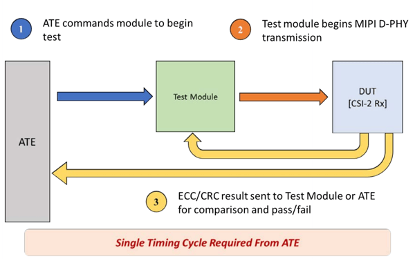
ECC means "Error Checking and Correction." CRC means "Cyclic Redundancy Code."
Figure 4. A test module enables testing MIPI interfaces with an ATE that can only produce 40MHz. The test engineer needn’t have prior knowledge. Arrows represent signaling designed to be friendly to the driving source.
(Image: Introspect Technology)
ATE-based solutions are possible for mass production testing of microcontrollers running ≥2.5 Gbps. The example ATE in Figure 4 is rated for 40 Mbps. To test a 2.5 Gbps MIPI CSI-2 input interface, the hybrid paradigm would use 40 Mbps to create very slow commands to the test module. Importantly the ATE vectors know nothing about MIPI CSI-2; they are just used to program registers into the test module.
Test engineers with no prior knowledge of MIPI specifications can use the load board test module. Referring to Figure 4, the orange arrow streams CSI-2 input from the test module to the DUT. Yellow arrows indicate error checking. The MIPI interface is unidirectional. If there are no other links on the DUT, a Joint Test Action Group (JTAG), I2C or MIPI I3C® interface can be used to check the cyclic redundancy check (CRC) error. The test module enables programming ATE vectors for a single timing cycle and at low speed (< 40 Mbps). When test module configuration is finished, it issues a simple command to “start transmission,” and the test module sends a complete CSI-2 protocol over the PHY at 2.5 Gbps or 4.5 Gbps.
Hybrid test modules can change the status quo with lower-cost solutions and cover increasingly difficult requirements. Test modules stress DUTs with a complete payload, thus improving quality assurance in a high-volume production setting.
To learn more about trends in testing, listen to the MIPI DevCon Taipei presentation “New Trends in the High-Volume Manufacturing of MIPI-based Devices” and download the accompanying slide deck.
Conformance Test Suite (CTS) resources are available to members for many MIPI specifications. Members can also become involved by joining the MIPI Test Working Group.